|
Our 00 layout is centred around a Beechingless Barnstaple - with the track based on its 'peak' and operable over a wide period of stock. In reality, HSTs did reach beyond Barnstaple - if only for filming, and now a GWR Class 143 is 'operating' at Torrington 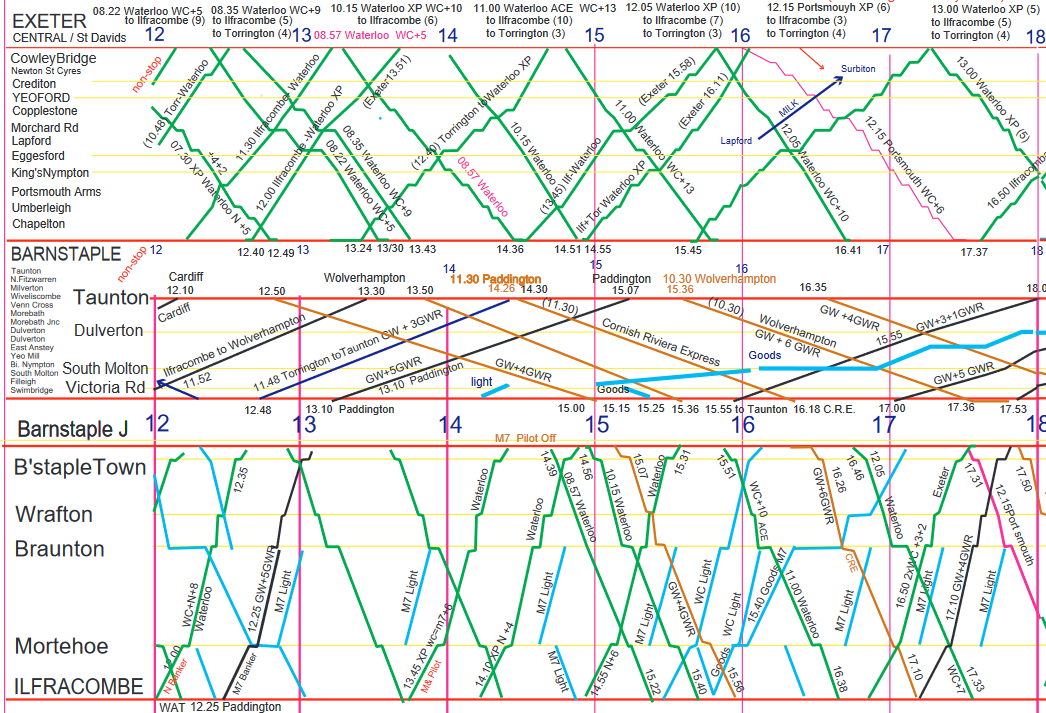 Part of a Graphic Timetable for Down Trains on a Summer Saturday in 1961 [downloadable full version below] PDF Downloads of Barnstaple Junction - North Devon - 1961 Timetable Extracts Graphic Timetable - Summer Saturdays 1961 Down Trains - Summer Saturdays 1961 Up Trains - Summer Saturdays 1961 Or Click on: G Scale Garden Layout or G Scale Portable Layouts (mostly seen at Hollycombe) and a Double-deck portable Scandinavian H0 Layout ALL of the layouts share the use of DCC control via Roco Multimauses and now Z21 Central Units. Beechingless was first started in the late 70's. 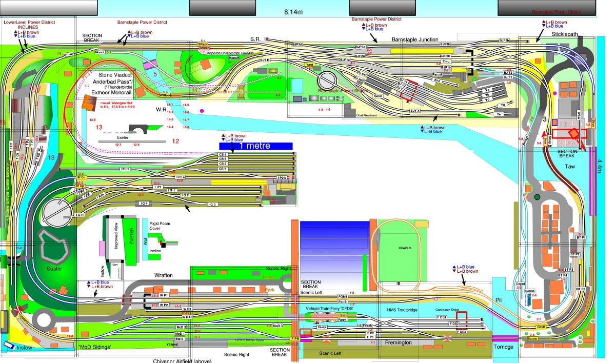 Beechingless Barnstaple Track Plans: Upper 'Scenic' Level and Lower 'Storage'/semi scenic Levels 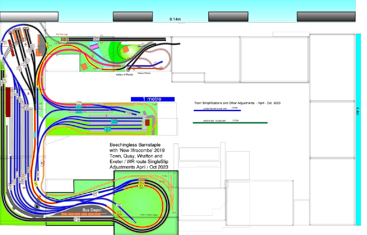
|
|
Beechingless v4b Semi-Scenic Storage Level 'Exeter' pictures - 2013+ after relaying with Rocoline Track Earlier 2 metre Zero-1 Micromimic Panel depicted 130 points & signals [ using all 99 codes available ] 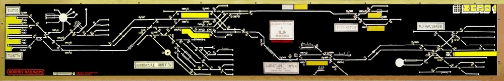 2-metre Zero-1 based Micromimic Display ( but using red and green LEDs ) - as used for the layout from about 1983-2005 This panel has been preserved and is on display in the garage where it can still be operated by a Zero-1 Master A DCC replacement using MERG steady-state decoders and spare Micromimic panels was built before large screens became economic and lightweight! Software-based 'Glass Panel' designs are much easier to update allowing easier modifications of the layout over the years.... Whilst especially true out in the garden, it also applies indoors for 'single operator' with full Accessory Control from the handset(s) Uncoupling and Shunting operations are best done in close proximity, and Route-Setting aided by screen displays is easily learnt by visitors at home or away. Z21 allows Android tablets to be used for touch-screen train and route control - whilst the Multimauses still offer single-handed 'unsighted' tactile control. 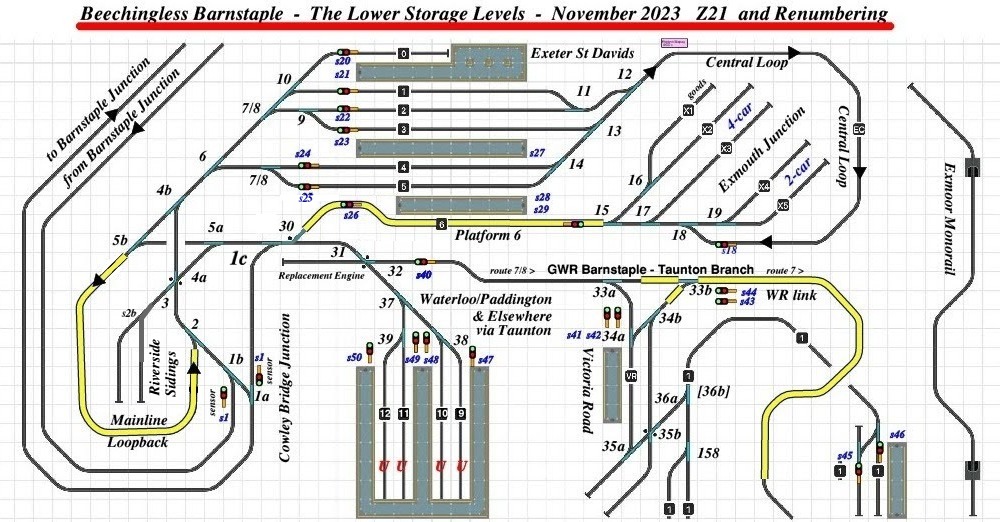
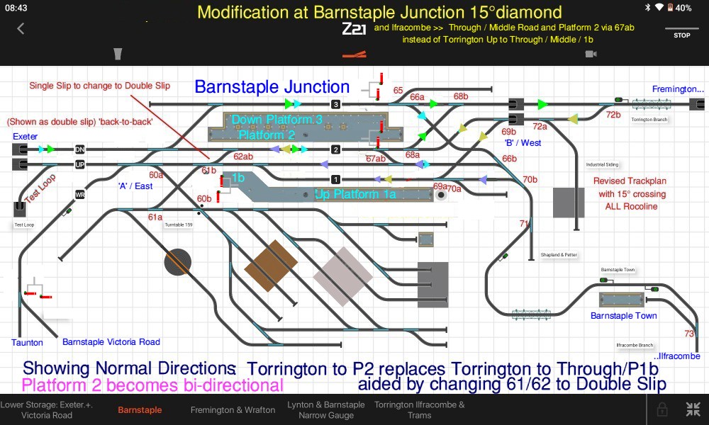
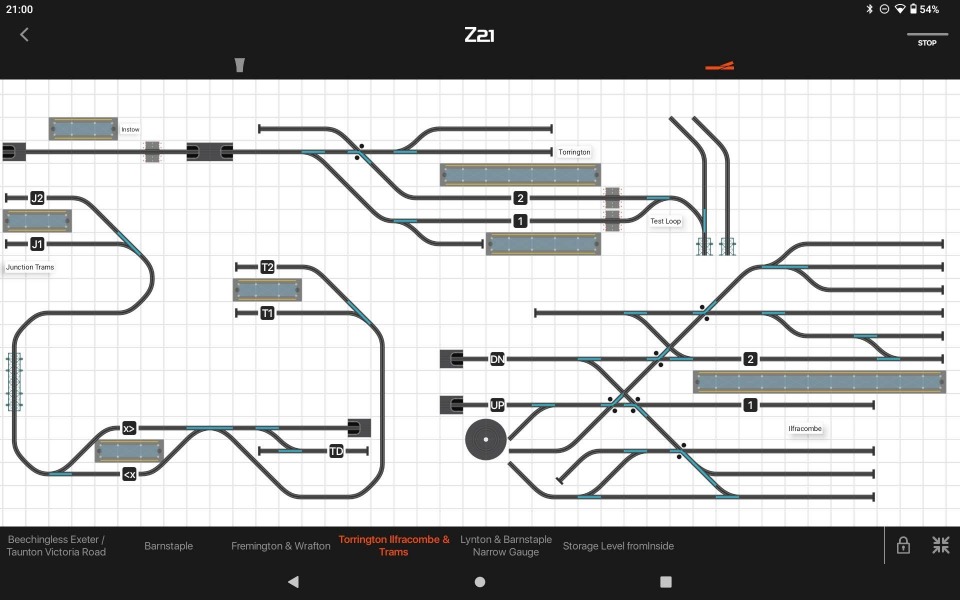
Examples of the zoomable Touch-Screen Panels designed for Beechingless Barnstaple are shown here. Each page is easily flipped-between. Routes can be set and displayed. 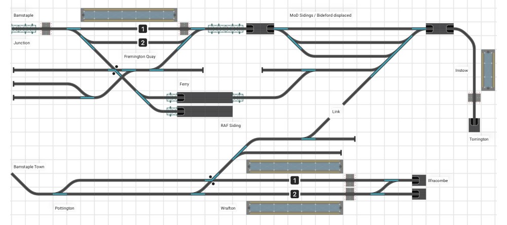
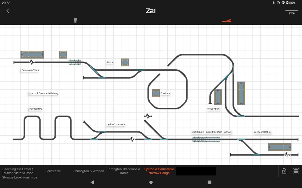
The Diagram below is a BBC BASIC Vector (zoomable) Drawing of the whole Trackplan - similar to the non-zoomable Rocomotion bitmap version It now requires updating to reflect recent adjustments... unless a copy of the Android's display is passed to a large communal screen ?? 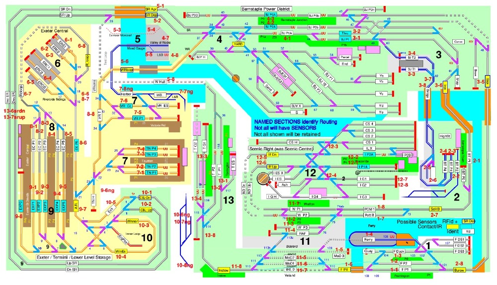
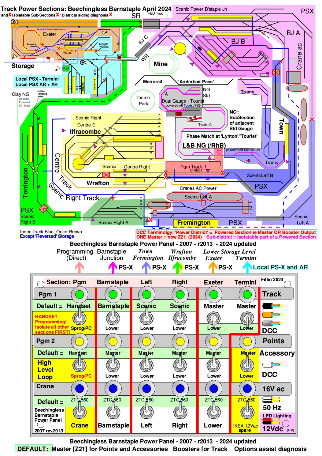
Wiring SimplicityDiagram of 'Power Districts' and their 'sub districts' Each 'Power District' has its own Power Supply and DCC Master/Booster with Rampmeter Voltage / Current Monitor and PSX Intelligent Circuit Breaker |
|
The MASTER DCC Central Controller directly supplies the DCC for all the Accessories: these are NOT via a PSX. There is minimal risk of a short circuit or excess of 3Amps. Multimauses + Power Panel replaced a 'Central Control Position' used by Zero-1/ZTC-411 Then Roco MultiCentralePro brought blue ZigBee Wireless Multimaus Pro Handsets Now Black Z21 with Black Z21 Wifi LANmultimauses are used for all our layouts but the displaced MultiCentralePro and Blue handsets can still be used into the Z21 Boosters are simply Roco 10764 Amplifiers with ONLY the Booster passive loop connection used. [The 'Amplifiers' and first Rocoline-with-Trackbed Track came in Starter Sets !] ALL are supplied from 18Vdc 4A SMPS Power Supplies and NOT the original Transformers!! 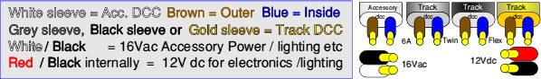
'6Amp Twin Flex' with differing sleeving colours is used for distribution: POWER DISTRIBUTION PANEL A Column for each Power Section: Programming Barnstaple Left Centre Right Store Top Row = Track DCC Middle Row = Accessory DCC Bottom Row = 16Vac Accessory POWER Centre-Off DPDT Switches with separate LED indicators wired on the OUTPUT ( eg track) side ) light if POWER is present: even if from a test battery touching the rails! An unpowered section LED will also light if the GAP to an adjacent powered area is BRIDGED Rampmeters give Accurate DCC Voltage and Current for each Power district - the change in current as a train goes thought sections is easily identified - the quiescent current of in-situ track-powered items is always visible for fault finding 'Power Saving' or Diagnostic Options: Sections can be powered directly from the MASTER (A =switch UP) or a Booster (B =switch Down) For much of the time only the Master need be powered - but dependant on coach lighting etc . Sections will follow on Using Video Cameras to monitor and record the railway operation: From early examples through Monochrome with 1.4GHz, 2.4GHz and now Digital 'Racing Drone' cameras. |
|
'New Sealink Ferry' Double-deck portable Scandinavian H0 Layout |
G Scale Garden Layout G Scale Portable Layouts (mostly seen at Hollycombe) |